Motorized Retractable Sails: Measurement Guide

To properly install your retractable sail, it is essential to take accurate measurements. Start by identifying the anchor points and estimating the distances with some tolerance. Once the anchors are installed, you will need to precisely measure the distance between them.

Following these guidelines will ensure a perfect and functional installation. Check out the complete guide for all the details!

How the Zefira configurator works

Thanks to our online configurator, we've simplified the purchase and installation process by dividing it into two distinct phases.

Each phase corresponds to a separate order, and you'll receive the materials in two separate shipments, maximizing accuracy and ease of assembly.

The 4 steps to buy Zefira:

PHASE 1

1

Configure your shade sail online

Identify the anchorage points and measure the approximate distances.
Configure your shade sail online.
In this phase, you only pay for Kit Phase 1, which includes all anchorages (poles and/or wall plates).

2

Receive and install Phase 1 Kit

You will receive the chosen anchorages, fabric samples, a measuring cord for precise measurements, and all necessary fastening materials. Install the supports in your outdoor space.

PHASE 2

3

Confirm the measurements

Visit the website and enter the precise measurements taken after installing the anchorages. Choose the fabric and purchase the second part of your order: shade sail, roller, and accessories.

4

Receive and install Phase 2 Kit

In just a few days, you'll receive your custom-made shade sail along with its roller, motor, wind sensor, solar panel, and all included accessories. The assembly is quick, straightforward, and entirely DIY.

How to take measurements

Accurate measurements are essential to ensure a flawless installation.

During the configuration phase of your shade sail, you'll be asked to provide measurements between the anchorage points. At this initial stage, extreme precision isn't necessary; a tolerance of a few inches is acceptable. These measurements help us calculate the optimal configuration and provide an estimated price for your custom shade sail.

After receiving and installing the Phase 1 Kit, which includes a professional-grade measuring cord, you can proceed to accurately measure the actual distances between the anchorage points. These precise measurements are crucial for manufacturing the custom shade sail and roller, and should be entered into your user panel before completing the purchase of the Phase 2 Kit.

IMPORTANT: All requested measurements refer to the anchorage points, not the fabric dimensions. The system will automatically calculate the fabric size based on these inputs.

Instructions for measurement and configuration

Measurements for the configurator

Use a rigid measuring tape to measure the area where you plan to install the shade sail, taking into account any obstacles such as walls, trees, or other elements that might affect the installation.

Measurement confirmation after installing the anchors

Utilize the measuring cord provided with your anchorage kit to precisely measure the angles and diagonals of your shade sail.

Ensure accurate measurements by keeping the measuring cord taut and measuring from the center of the anchorage hole.

Note: When measuring for the roller, account for its potential tilt and the final anchorage height.

How to identify side AC (roller tube)

The AC side is conventionally referred to as the roller side.

In a quadrilateral (a shade sail with four corners), the AC side corresponds to the diagonal.

In a triangle (isosceles, scalene, or equilateral), the AC side corresponds to one of the sides.

In a right triangle, the AC side corresponds to the hypotenuse.

Example: quadrilateral

Example: isosceles, scalene, equilateral triangle

Example: right triangle

Motor at point A

Point A is the location of the motor and the main reference point for configuring the shade sail.
By defining this point first, you can precisely position the other fixing points for a correct and balanced installation.
Point A should be the highest point of the roller tube.

Roller tube measurement

The length of the roller (AC side) has a tolerance of 1 inch per side. This measurement must be taken with extreme care in PHASE 2, once the anchors are installed.

WARNING: See angle A and C degree restrictions in the specifications at the bottom of the page.

Sail inclination

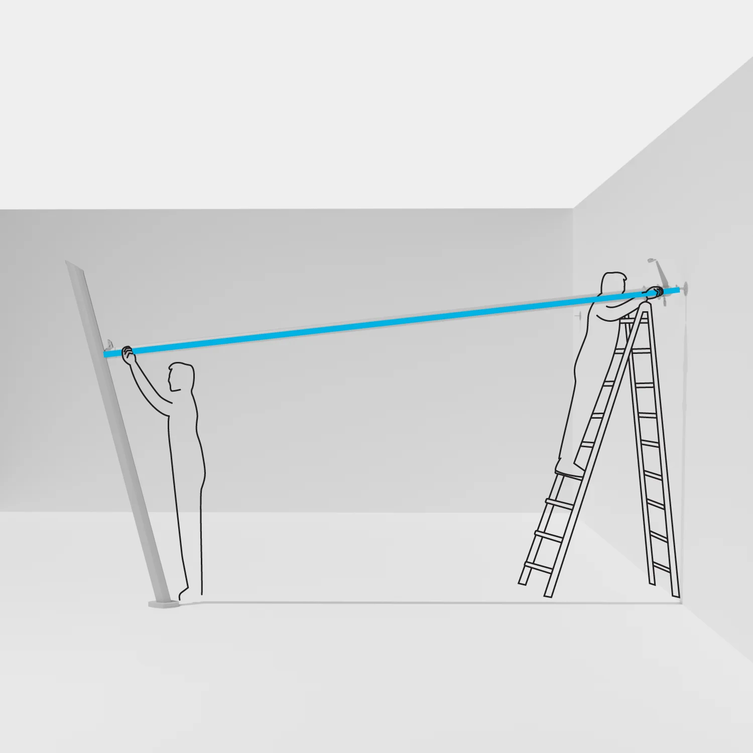
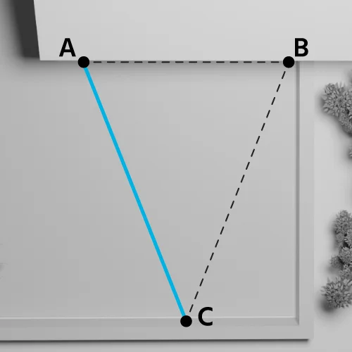
The roller can be tilted.
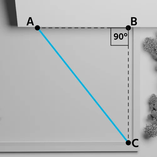
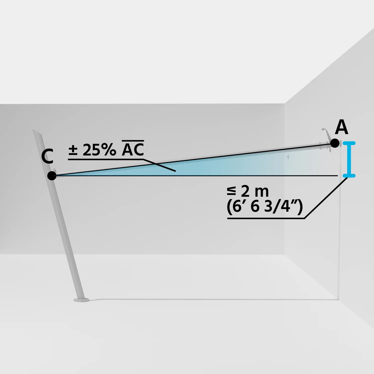
The maximum allowed tilt for the AC side is ± 25% of the roller length.

Example:

If the roller (AC side) is 8 meters long (800 centimeters),

Maximum tilt = 800 / 100 x 25 = 200 centimeters

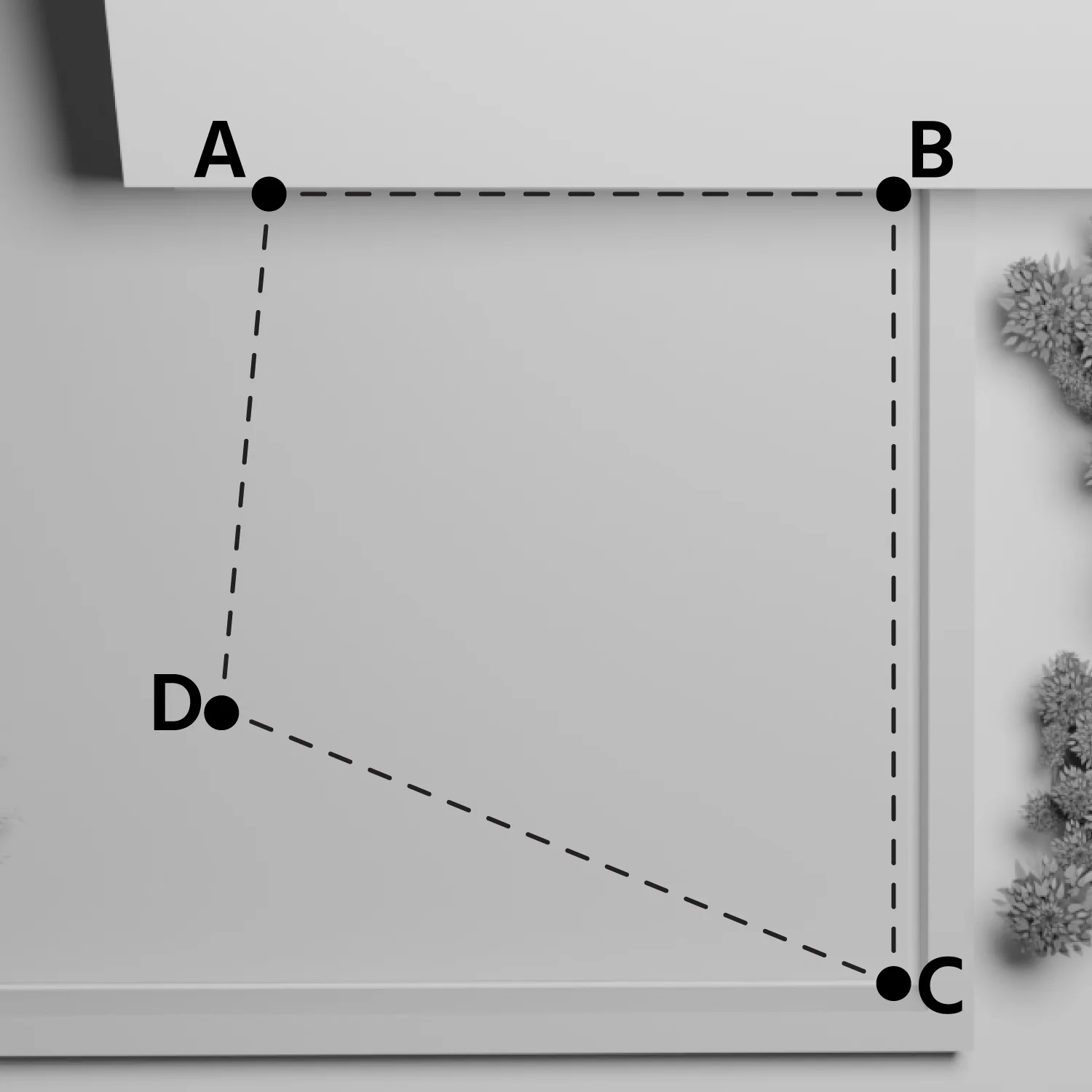
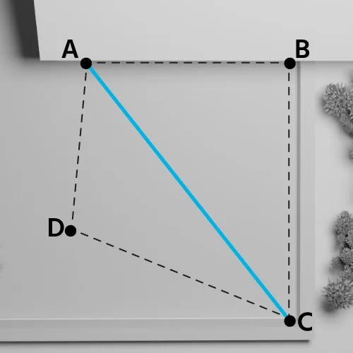
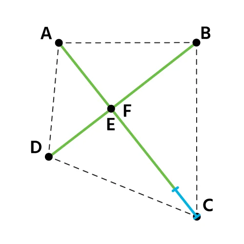
IMPORTANT: If you choose to install the shade sail with a tilted roller, the actual distance between corner A and corner C will be greater than in a perfectly horizontal installation. This happens because tilting the roller increases the length compared to a parallel-to-the-ground setup.

TIP: It is recommended NOT to tilt the roller towards corner A, as it holds the motor.

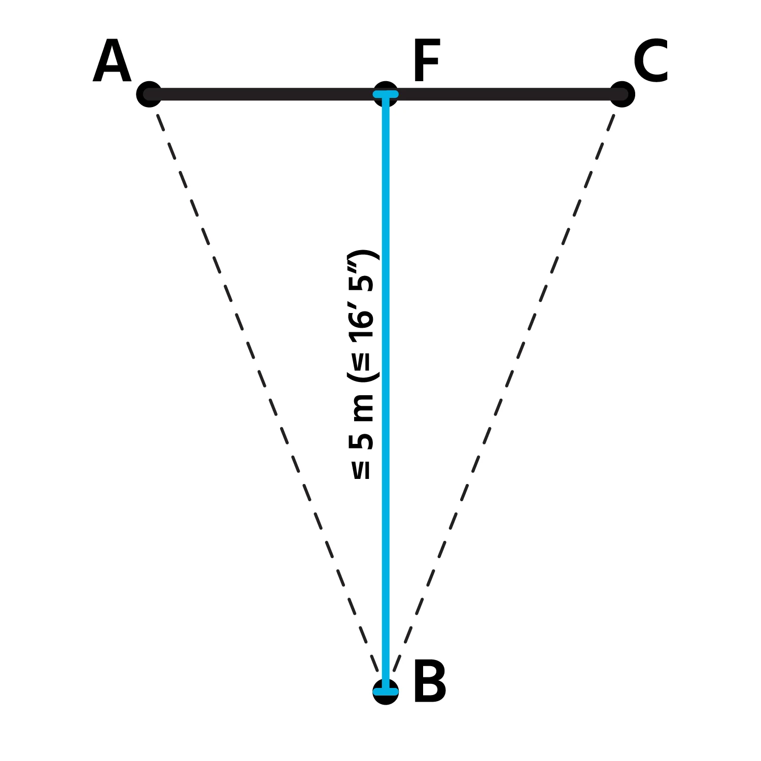
NOTICE: Motorized roll-up shade sails must be installed with a proper inclination to ensure correct drainage of rainwater or hail. It is necessary to tilt the roller and/or one or more corners of the sail to create a slope of 25%.

Constraints in the production of the motorized retractable sail

General Constraints

To ensure the successful completion of the project, it is essential to follow certain technical constraints during the design of the motorized retractable shade sail.

  • Angle A: It is always the point where the motor is installed, serving as the main reference for the entire setup.
  • AC Side: This diagonal corresponds to the roller and must meet specific measurements to ensure the stability and optimal tension of the sail.
  • AC Side Dimensions:
    • Minimum length: 7' (210 cm)
    • Maximum length: 26' 3" (800 cm)

Special Constraints for Triangular Sails (Shape: Triangle)

  • Maximum Area: 215 ft² (20 m²)
  • The BF side, perpendicular to the AC side (roller), can be a maximum of 16' 5" (5 meters). (Figure 1)
  • Angles A and C must be less than or equal to 85°. To simplify, angle B must remain within the shape of the roller to properly roll up. (Figure 2)

Figure 1

Figure 2

Special Constraints for Quadrilaterals (Shape: Square, Rectangle, Trapezoid)

  • Maximum Area: 323 ft² (30 m²)
  • Angles A and C must be less than or equal to 85°. To simplify, angles B and D must remain within the shape of the roller to ensure proper rolling. (Figure 3)
  • The difference in length between the DE side and the BF side must not exceed 20 inches (50 cm) in length, as shown in Figure 4.
  • The AC side (roller) must always be longer than the DE and BF sides, as shown in Figure 5.

Figure 3

Figure 4

Figure 5

Download the printed guide and note the dimensions we will ask for during the configuration process.